Electronics - a personal history
Lessons hard learned
After high school, 18 years old, I was in my first year of electrical engineering at the Eindhoven Technical University. The first lectures were 'a recap of high school', and pretty quickly I started learning some first class maths and engineering. At the same time, I started my first business rbqline: 'r' and 'b' are my initials, 'q' sounded funky and 'line' sounded smooth. During high school I had taught myself HTML/CSS/JavaScript/PHP/SQL (Netscape Navigator to the rescue!) which led me to make some websites for friends of friends. My first big commercial project though (which turned into them ripping me off completely, but okay) was for a solar studio of my brother's partner in crime. In this Sun Valley project I engineered all software and hardware. I made the website. I made GUI software (in Visual Basic 6.0) with database backend to store all customers, which contained a payment system with a lot of additions that kept growing and turned the system into a time bomb. I was often called mid-lecture by the solar studio's owner that the system had crashed (him reading the error from the screen), and that they couldn't restart the PC because it would turn all the solar benches off. I then took the train back home and quickly went in for some on-site bug fixing. Often with a queue of angry customers and solar studio workers looking over my shoulders.
This software was also coupled to another PC/TV combination over the network that showed the availability of the benches with colorful images of the sun. It was also coupled to a Velleman K8000 LPT-interfaced relay card that could turn the benches on and off. Yes, parallel port! There also was a music 'streaming' system for which I made the hardware. This system (dubbed the Sun Valley Pulser System by me) could switch between 8 incoming audio signals (from 8 discmans at the counter) by means of push buttons. It used a CD4051B as octal analog switch and a X9C104 as digital potentiometer. It was so badly designed that it suffered from all possible combinations of problems. To add insult to injury, the implementation was even worse, with bare wires running through the building everywhere. The project dragged on for two to three years during which I made max. 5000 guilders. I learned a lot though, especially about setting limits and recognizing manipulation.
Start of a hobby
At around the same time, I started making audio electronics. It was the time we were exploring 60s-80s rock music and played in a band (was I the worst singer they had?). The most logical choice for useful electronics was something I could listen to. Also, you really think I had the money to buy a scope? Audio is low frequency and thus relatively insensitive to bad wiring. I thus piggy-backed 'n hacked my way into the first audio effects, amplifiers etc. Unfortunately, some years later my hard drive crashed that contained pictures of those early masterpieces (thank you Merlijn for returning the borrowed hard drive with an adapter with the correct plug, but too high voltage). Years later, I must have been amused by the sheer professionalism of my younger self, and made a couple more pictures. At that time I lived in Nijmegen with two girls who must've been scared now and then by my DIY practices. I did make some electronics there, and in the meantime had also aqcuired an old analog scope that I bought from a nearby university.
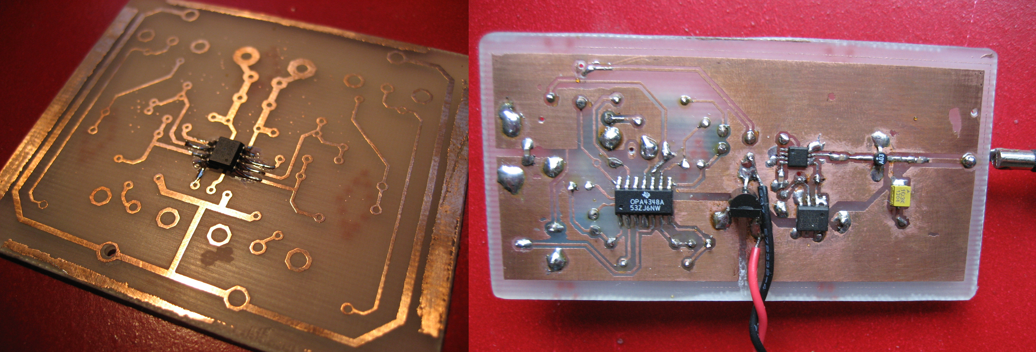
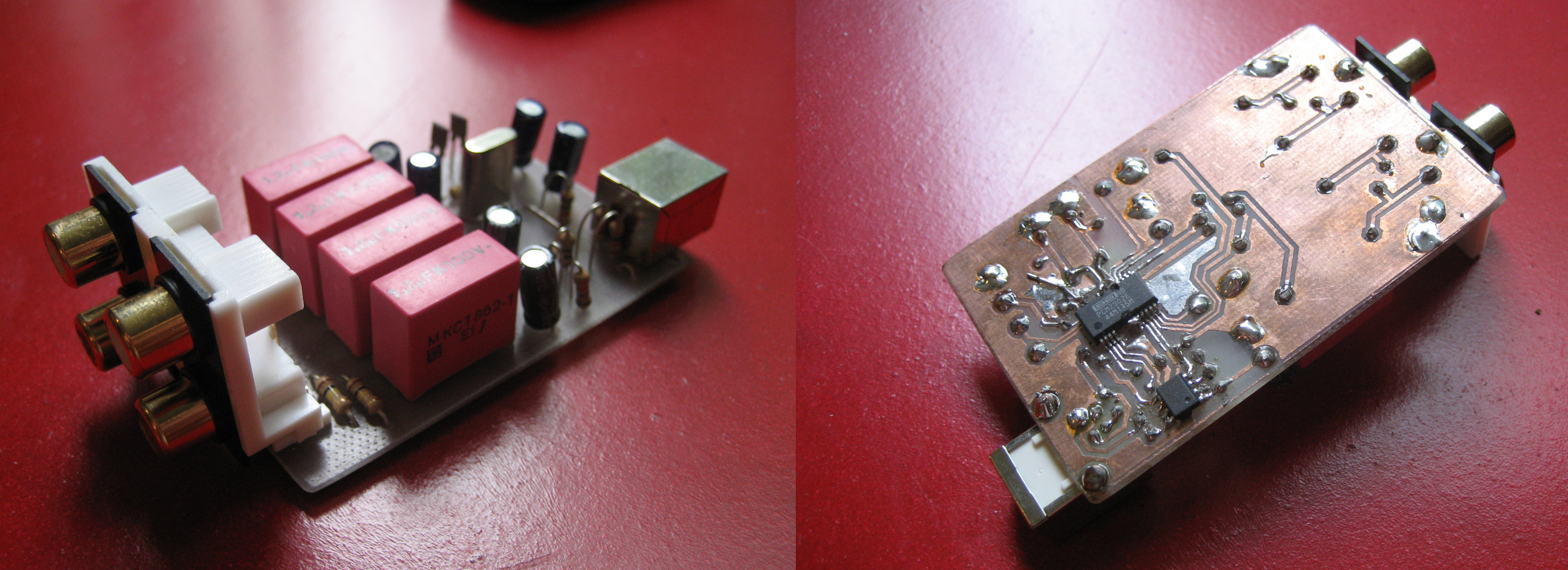
I made my PCBs by heating a solution of sodium persulfate in the microwave, using my roommate's glass lasagne tray (when she was not at home). When the tray was hot to the touch, I submerged the PCBs (cut to size and with press-n-peel'ed mask from my precious HP 1018) in it and watched the etching process, carefully moving the PCBs around with some nifty blue plastic pincers. I had very little to do those days. The PCB on the left is, it looks like, the beginning of a phono preamplifier that I made for a turntable my dad gave to me. It looks like: two RCA connectors in, two out. Probably a Burr Brown or Texas Instruments op-amp, since they gave almost unlimited free samples in those days (I never bought any ICs). All PCBs with hand drilled holes, the horror.
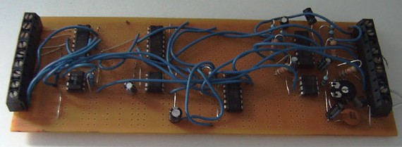
On the right you see the culmination of a project for my dad, who was very annoyed with people calling on their mobile phones in the train and requested me to build him a jammer. This one worked, albeit only when the phone was within 10 cm of the jammer, which was not the most straightforward use case. Still I was proud (no I wasn't, I am now!) to make this thing even work, given that it was completely hit-and-miss type of project. The "jammer" consisted of a triangular waveform generator (plus a noise source, if I remember well, where I used a BJT with one leg dangling in the air) which was fed into a VCO (the SOP-8 thingy) and then into an LNA which I, again, sampled for free but was actually meant to be used as an input amplifier instead of a power amplifier. Well, at least I had an idea of some of the problems I was facing. Also, the PCBs tracing and grounding scheme (which one?) might be considered at least sub-optimal. I tried to pull some wideband power amplifiers from old mobile phones I bought at flea markets, but never got around to implementing them. I reckon that by the time my dad had gotten used to people calling on their phones anyway.
Audio amplifiers
My first power amplifier was built in my bed room in Remunj and was based around some chip amp. I was heavily leaching on diyaudio.com those days, and chip amps were HOT. They were the bomb. Or at least, that's what people said and they had a large following, most probably because these amplifiers were terribly easy to build and anyone could do it. Even me in those days. And so I did. The one pictured here features a Texas Instruments (free samples, remember?) stereo amp, probably an OPA2544 or so, anything that was quite in on the forum. I did, however, not include snubbers in my power supply (people were going mad about them!) because even my 18 year old self deduced that that was BS.
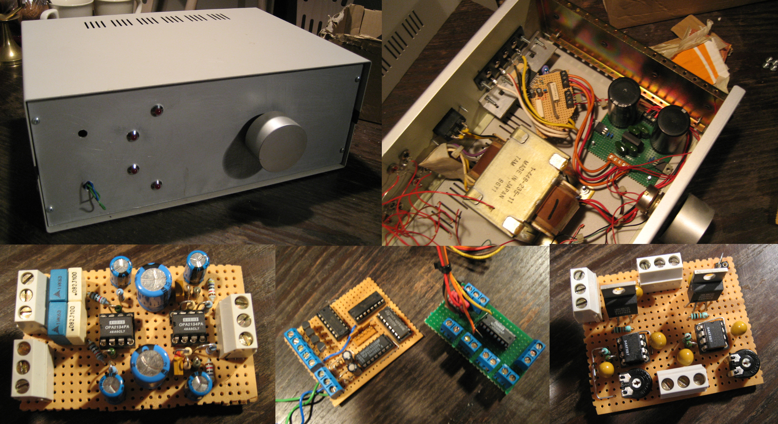
The picture shows (top-left) the amp as we used it in our living room and the insides (top-right) with only transformer, power supply and power amplifier board left inside. The three pictures on the bottom show, best guesses, from left to right: OPA2134-based RIAA pre-amplifier, logic board for input switching and (drums please) the completely overhyped input stage for a chip amp based on 2x OPA637 and 2x BUF634. If I had paid for the chips, it would've been a waste of money. It was a lot of fun to build and listen to, though. I remember playing the first tunes through this amp, on two of my mum's old (Wharfedale?) speakers. I was amazed that I could build something like that at home. Later I was amazed that I used it as my main living room amplifier.
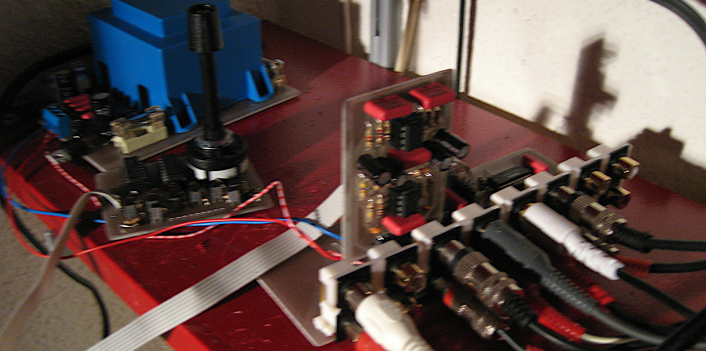
After I decided that the chip amp did not live up to expectation, I made a solid state amp after a design by Douglas Self (no pictures, unfortunately). The picture you see above are the preamp (with RIAA board sticking up) and logic board that read out the rotary switch, decoded it to 3 bits and sent it to an analog multiplexer located on the preamp board in the front. Everything was heavily opamp based and it sounded good. The power amp was very short lived (don't remember the details), and I ordered PCBs from Rod Elliott to make myself a P101 with vertical MOSFETs.
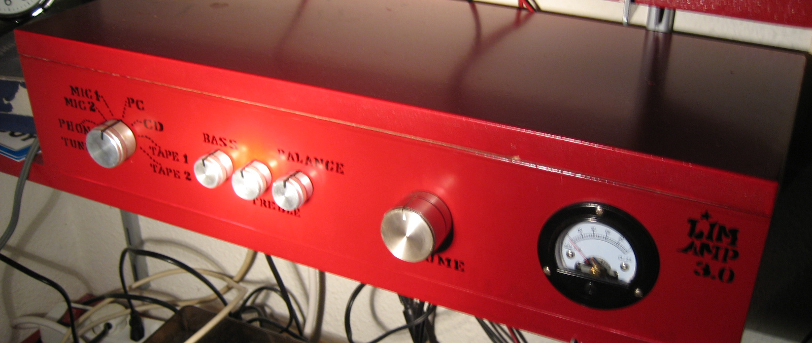
The picture of LimAmp 3.0 shows the top of my artistic capabilities at that time. All lettering is hand drawn using a marker. I must've also made an equalizer for this thing, judging by the bass/treble/balance knobs, and indeed my memory tells me it was in there - fully opamp based again. This was also a design that heavily borrowed from Rod Elliott's designs. The analog level meter on the right never worked properly, and honestly I didn't care much about that. I have enjoyed this amplifier for about ten years! First with crappy speakers, then with some Quadrals. In the last three years of it's use I ditched the preamp for a Chinese integrated one (which had S/PDIF and USB inputs) and which sounded better anyway. The power amp (the P101) is still at my dad's in storage. Wonder if I will ever listen to it again...
Effects & instruments
I did tell you I used to be in a band, didn't I? Well I can't play any instrument, nor do I sing particularly well, but apparently I can catch the attention of an audience. Is that enough to become the singer of a cover band in a rural Dutch town? Yes it is. And so there were instruments (electric guitars) and microphones, and the possibility of putting analog effects in the signal chain. And so it went.

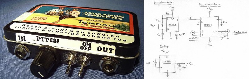
The breadboarded circuit on the left was a delay/echo based on the HT8970, which sounded absolutely horrendous. I enjoyed making the enclosures much more. The preamp was just a simple voltage amplification. The style of the lettering follows the LimAmp3 style, a style that I recently used in a logo design. The Boss CE-2 clone on the right, however, was a lot more fun to build. It features some BBD chip and a lot of auxiliary circuitry. We built it in a day or so and tested it out by playing the guitar through the effect onto a scope and made a video of it.
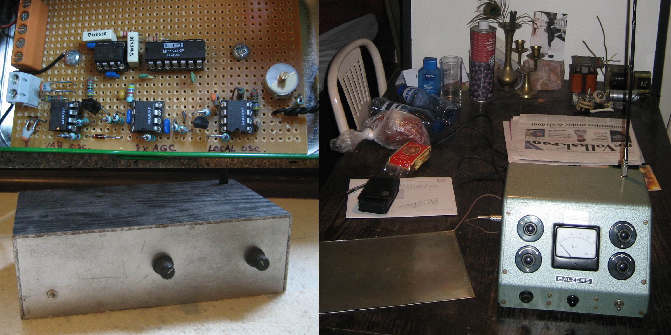
Apart from modifying signals in the signal chain, I also created some signal sources. Some people'd call them instruments. Tonie kept on talking about Theremins, and I figured it should be straightforward to build one, so I promised him one. It took me some years, more off than on, to get to a somewhat working version. I figured it'd be easiest to reinvent the wheel and not recreate a known design. Well, naivety can be a good teacher. Theremins are most often made by mixing two high frequency oscillators (ca. 500 kHz) of which one is of varying frequency and extracting the difference (audio) frequencies by low-pass filtering. The mixing can be done by summing the oscillator sources and passing them through a non-linear element. I thought I'd be smart and semantically pure and multiply them with an analog multiplier, so that's the function of the MPY634 in the top-left of the picture. The bottom opamps are the two oscillators (left and right) and a double automatic gain control (middle). The uA741 to the left of the MPY634 is the LPF that filters out the audio frequencies. And yeah, it worked. The electronics in action you can watch here and here. Some time later I found a nice retro box (on the right in the picture) in a dumpster and decided to put the Theremin in it. I added some additional shielding and now had a well working instrument! Check it out here. My grandma even played it and was a bit freaked out by it. Finally, I must've given it to Tonie for his birthday. (Do you have it still?)
Going digital
At a certain point I slowly moved into digital electronics, mostly related to audio of course. In the picture below you see my first (working) USB audio card based on some Texas Instruments chip of which I had a lot lying around (free samples, anyone?). This one uses a PCM2902, and it gave me massive headaches. Etching and soldering TSSOP pitches was not something I had done before and I did not have the right equipment for. Also, making it work on a single layer board (no ground plane!) proved troublesome. It remained a bit buggy, probably because of that.
The years following I didn't make much electronics. I moved to Utrecht and didn't have a proper workplace there. So only after I moved to Amsterdam, did I start to pick up on electronics again. At that time it had become easy to order PCBs from China and so I started designing and ordering two layer PCBs. Before I ditched the preamp for the Chinese one, I designed an input module for my amplifier that could switch automatically between multiple coaxial S/PDIF inputs and do the D/A conversion. The switch (don't remember what chip I used) was controlled by an Arduino micro that could sense which digital input was receiving data. Via a priority based scheme, it would then select the active input with the highest priority. This worked pretty well, and I used it for a little while until other parts of the preamp started dying and I tossed it all out and bought the Chinese XiangSheng DAC-01A which I still have.
Slowly going pro
In those last years I was a doctoral candidate (in chemistry), and so I was rapidly becoming a professional scientist. Combined with my engineering background I quickly transformed my tinkering habits into much more thought-out electronics.
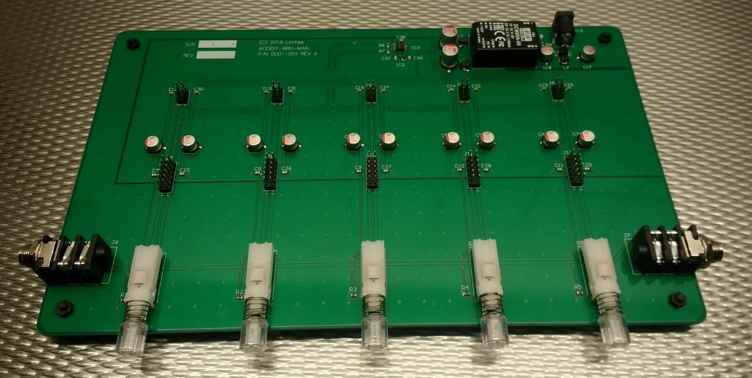
One of the projects I have been working on in recent years, is a modular approach to guitar effects. It allows for manufacturing of guitar effects as plugin boards. As such, the effects themselves can be made cheap, since it is only a PCB with some connectors and potentiometers. The motherboard can be made rugged so that you can turn it on/off by foot. It is in a box somewhere, waiting for me to pick up on it.
Professional engineering
After my short-lived academic career I worked as an electronics engineer and technology development engineer. I designed and implemented software, firmware, hardware and automation setups. The electronics I developed during these years ranged from high-end analog instrumentation to mixed-signal platforms for automation of chemical processes. Because these designs are not open, I will not provide any details.
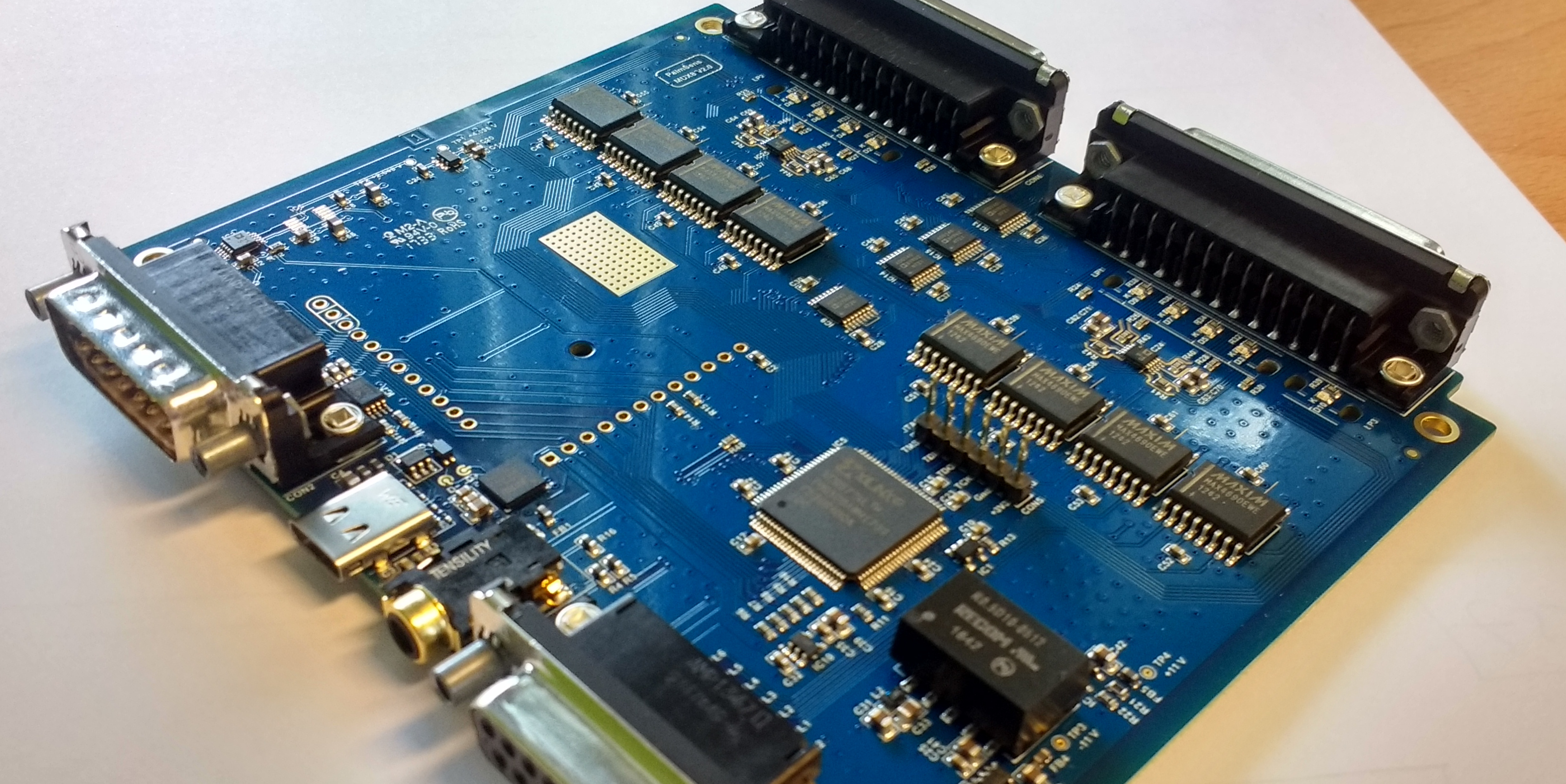
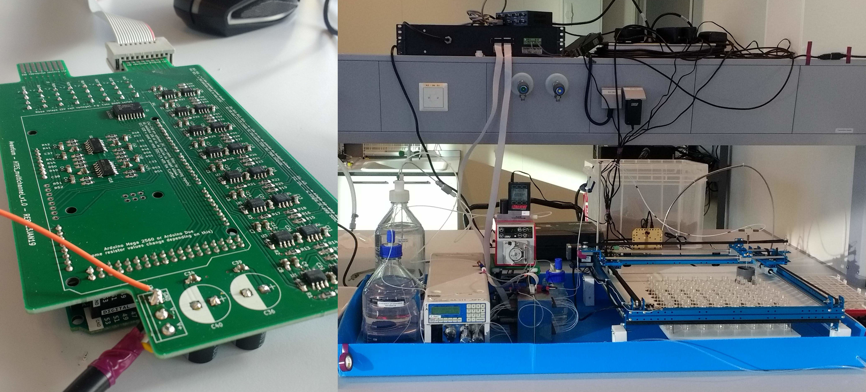
Apart from a wide range of electronic hardware, I wrote firmware in C (calibration protocols, communication protocols) and software in Python for hardware interfacing, automation and data analysis. I have fallen in love with this combination of hardware and software. Controlling electronics through computer code, and the analysis of data generated by the electronic interpretation of real world systems, it's just the most fascinating thing in the world.
Sabbatical
The northern hemispherical winter of 2019/2020 has turned into a sabbatical. My partner and I moved to Sydney for one year where she conducted research at the university. After applying and networking for three months I was unable find a job. I did however manage to finalize some coding projects that needed my attention. I also discovered some great youtube channels (thanks Simon!) in that time.
Since that first commercial project at Sun Valley, I had been fantasizing of having my own company. Be my own boss, etc. One of those days in Sydney I woke up, and being so fed up with looking for jobs I decided I go look for studio space somewhere. I called a creative space in Redfern and visited the same afternoon. They did not have studios available, but the seed that had been planted years ago, suddenly sprouted. There was no stopping now. I found a MakerSpace in Marrickville, visited a couple days later and within two weeks I had a studio space (6 m2) and registered my company organic.audio. For the last 8 months I have gone through a very important process, where I have reconnected with my creative side. I have, in short, learned to merge my creative and technical side to produce a bluetooth speaker that sounds amazing and looks great. I learned wood working, by hand and with the CNC router.
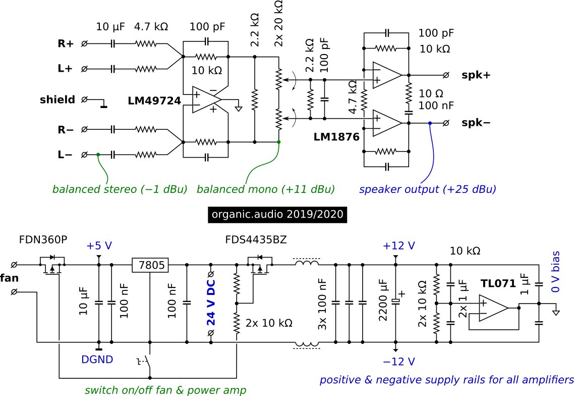
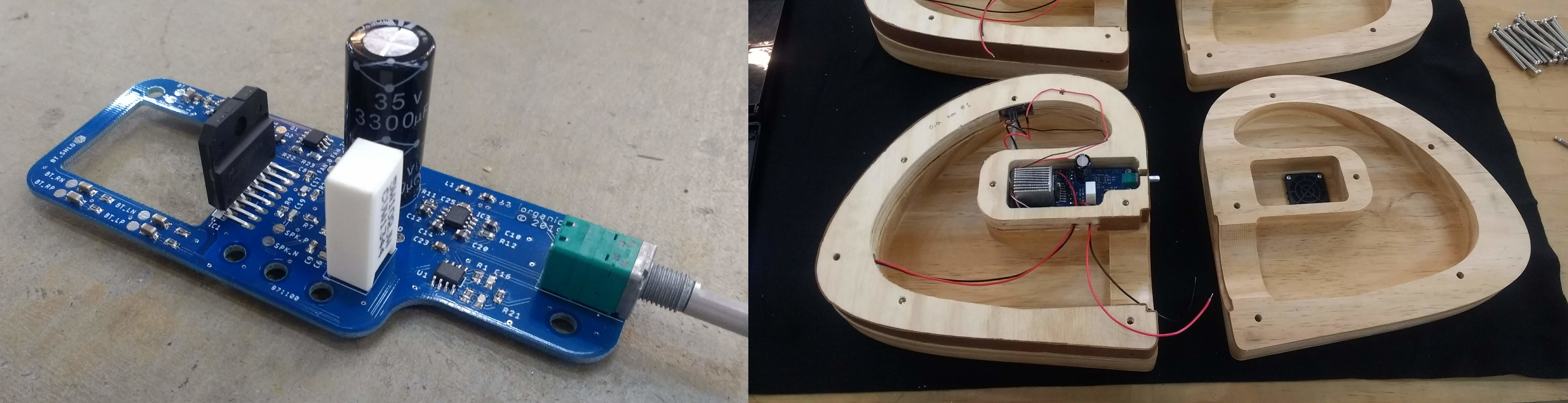
You won't believe it: inside the organic.audio speaker is a chip amp! But this time with a proper design. The speaker is mono, and the LM1876 stereo power opamp is used in bridged configuration, driven by a balanced bluetooth source that is left-right summed to mono and amplified by a LM49724. A switch in the volume potentiometer turns on the fan and enables power to the amplifier. The bluetooth receiver is always on, so that it stays paired when the amp is off. The configuration of the amplifier is designed around the requirement that it should run off a commercial 24V adapter. I use it to power a single 15 W driver, and it sounds a-ma-zing.
Where I stand now, I am very satisfied to have created a product of high technical ingenuity and with a design that I a never knew I was capable of. Another important thing that I learned, is that having my own business is not what I should pursue. I perform very well 'behind the scenes', but suck at PR, marketing and sales.
"I hope you've enjoyed reading it." - René Becker - May 7, 2020 - Coogee NSW, Australia